|
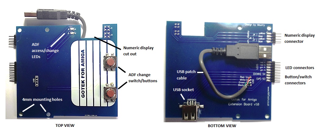
Gotek Extension Board by KMTech Design Installation Instructions - Kit Version v1.0 and v1.1 Hi, my name is Kevin, and I am the designer of the Gotek Extension Board. I have an eBay store where I sell lots of unique accessories for retro computers. If you are interested click here. These are the installation instructions for the KMTech Gotek extension board. I considered doing this in a Youtube video format, but that is not a good idea unless one is skilled at video production, which I am not. Also, you would have to put up with my funky Northern-England accent, also not a good idea! I am going the refer to the extension board as the EB from now on, because I am a man so therefore inherently lazy. Similarly I'm going to refer to the Gotek board as the GB, so by the end of this guide you will definitely have the EB-GB's ;) JUST WHAT IS A KMTECH GOTEK EXTENSION BOARD ANYWAY? The Gotek solid-state diskette drive emulator is an innovative device, capable of attaching to a computer and pretending that it is a real floppy drive. However, it does not use conventional floppy disks to hold data, instead it holds virtual floppy discs, in the form of image files, that it accesses from devices such as memory sticks that plug into it's USB port. One day along came a clever fellow who made it work with the Commodore Amiga. All well and good, but the Gotek drive was never designed for this. It just wasn't the right shape. If you installed it inside an A500 or A1200 casing, you couldn't access the buttons properly, or see the display or LEDs. If you installed it outside the case it was more accessible, but rather unsightly. The main problem with all this, thousands of valuable Amiga cases were being drilled, cut and otherwise butchered just so the owner could see the numerical display etc. We at KMTech noticed these problems. We had a think and said hey, why not have the Gotek inside the case where it can't be seen, and have the controls outside where they are accessible. And why not give it a retro look, in keeping with the Amiga itself? And Lo - the Gotek Extension board was created! Here is a top and bottom view of the board. You will see that it deliberately has the look of a 3.5" diskette but with added features: |
|
INSTALLATION OVERVIEW As installations go this is quite a simple one. Approximately 75% of the work is done for you i.e fitting the USB socket, surface-mount LEDs, pin headers, button switches and USB patch lead. These components have the following functions:
The remaining 25% of the work is down to you. This work can be divided into six tasks, which are carried out in the following order:
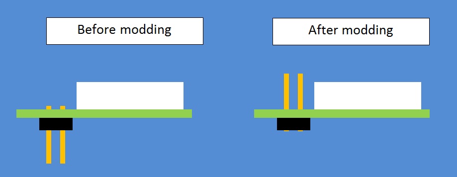
1. MODDING AND ATTACHING THE NUMERICAL DISPLAY. This is by far the most challenging part of the installation. You will be modding the four pin headers in the numerical display so that the display will fit into the EB. Then you will be actually soldering the display into the EB. Fear not! This is much easier than it sounds as long as you follow my instructions to the letter. Take a look at the picture below. It shows a side view of the numerical display before modding, and then after. Before modding you will see that the four pins are only just clearing the top surface of the display pcb. In the modded display the pins are sticking out much further, far enough to protrude through the holes in the EB for soldering. |
|
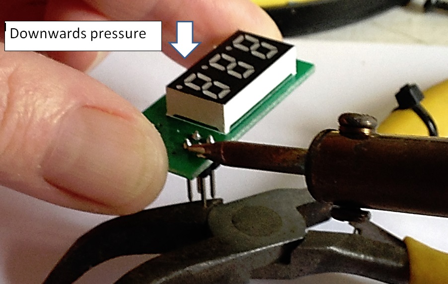
Moving a pin header like this simply involves a light touch with the soldering iron. This is how I do it (please refer to the pic below). You may prefer another method but this one works for me:
|
| After you have soldered all four pins back up, it's time to install the display into the EB. There's not really much to say about this except make sure the top surface of the display is flush with the top surface of the EB before you apply any solder. You may want to remove the protective film from the top surface of the display. When you've finished you will have something like this: |
|
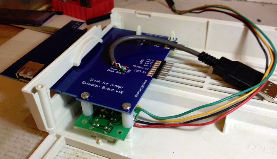
MOUNTING THE EB. The mounting of the EB is different depending on whether the host computer is an A500 or A1200. On the A1200 the mounting points for the system LEDs are used along with two self-adhesive pillars. Two extended screws and 12mm nylon spacers are supplied with the kit for this purpose (see pic below). A1200 MOUNTING |
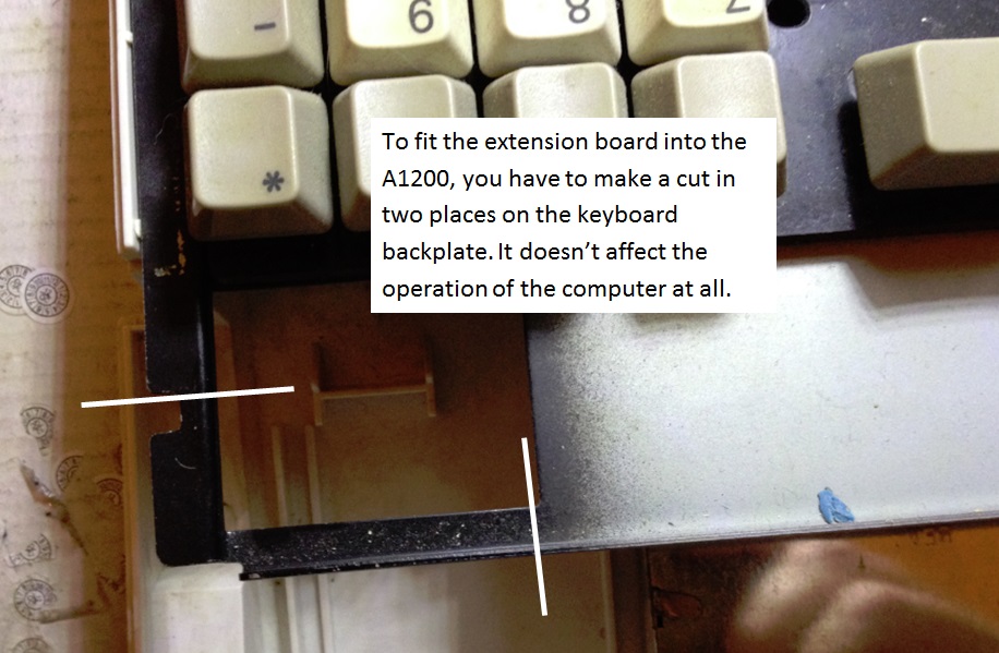
| In order to mount the EB inside an A1200 it is necessary to make a slight modification to the keyboard backplate. Fortunately there is no downside to this, as the piece to be cut out serves no purpose, and is very easy to remove with a handsaw (I used a rotary cutting disk on the end of a power drill). |
|
A500 MOUNTING Unfortunately there are no convenient mounting points on the A500 so 4mm self-adhesive mounting pillars are used in all four mounting holes. Although we supply double-sided sticky pads we recommend that you bond the pillars to the inside of the A500 case using a binary adhesive such as epoxy resin. When installing the EB inside an A500 take care to get the positioning right. Positioning is not critical, but try to get it "half-in, half-out" and make sure it is squarely fitted and that the LEDs can be seen from the outside. Two of the four A500 mounting pillars are long and two are shorter. It will be evident which way round these go during installation.
|
| ATTACHMENT OF WIRES TO THE GB
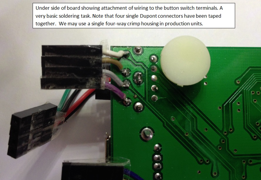
BUTTON SWITCHES. We now turn our attention to the GB (you still remember what the GB is don't you?). Turn the GB over so you can see the underside of the board. Look for where the four terminals from the two button switches are soldered. Solder the four wires from CH1 to the four terminals as shown in the photo below. Note that the wiring colours may be different on the connector you get, but it won't make any difference to the operation (and because this wiring assembly is so short you won't be able to plug it in the wrong way round, and even if you did it wouldn't make any difference!). |
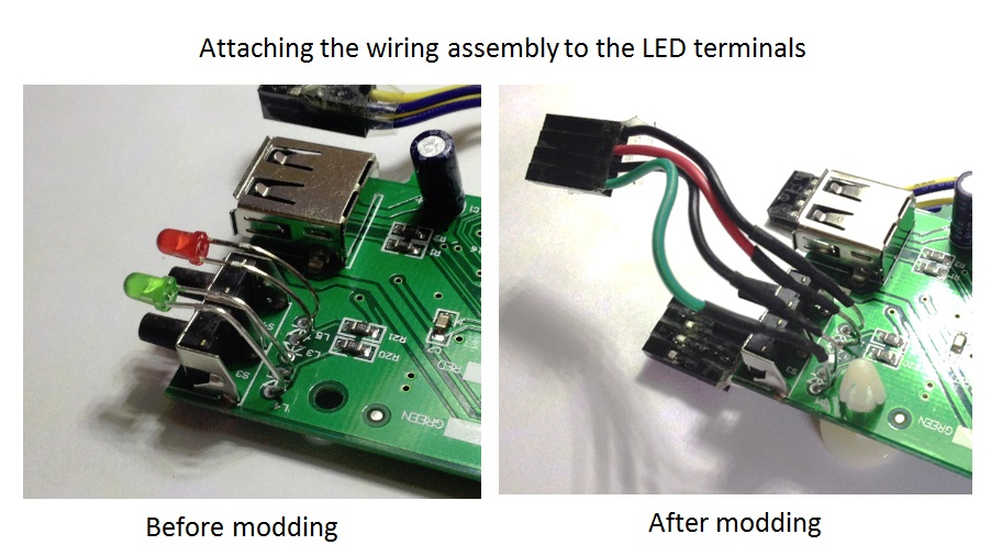
| ATTACHMENT OF
WIRES TO THE GB LED TERMINALS Take a look at the photo below. On the left are the unmodded Gotek LEDs, and on the right the LEDs after modding. You will see that the heads of the LEDs have been removed completely. After clipping off the heads (leaving as much wiring as possible), slide a piece of 1.6mm heat shrink tubing down each of the four wires (these have been provided in the kit). This is important, because there is a chance the wires may touch each other during the installation process and short out. If you don't have access to a heat gun, you can use insulation tape instead. Take the LED wiring assembly (identified by having two black wires, a red wire and a green wire) and solder the four wires to the four LED terminals as shown in the photo (This is the easiest of the three soldering tasks. Slide the heat shrink tubing over the soldered joints and shrink them with the heat gun, taking care not to apply heat for longer than is necessary (to avoid damaging anything on the board). TIP: Whilst we are on the subject of LED terminal modding, this might be a good time to mention a tip that will make the two boards mate together more easily. If you bend the four pins so that they point upwards, the two boards will align with each other better. 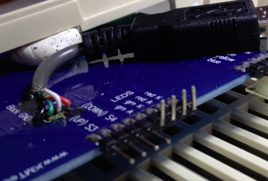 |
| Mounting the GB. The GB mounts inside the A500 or A1200 the same way - five adhesive pcb mounting pillars. The pillars provided are for 4mm holes but unfortunately the holes in the GB are 3mm, so you will need to either: Drill them out to 4mm. This is very easy to do as there are no tracks near the holes. Or Buy 3mm mounting pillars. "Why didn't you supply 3mm mounting pillars in the kit", I hear you cry. I couldn't source any is the simple answer. You might have more luck than I did. Use the double-sided sticky pads if you wish but as with the EB I recommend that you bond the mounting pillars to the Amiga case using epoxy resin or similar. Using the photo below as a guide, mount the GB in the case adjacent to the EB. It may be hlpful to attach the numerical display, LEDs and button switch wiring at this time, but not the USB patch lead, Gotel data cable or Gotek power cable, as these may tend to push the boards out of alignment. If you are using epoxy resin or similar adhesive, anchor the board in place and leave for 24 hours before attempting to attach the remainder of the wiring. |
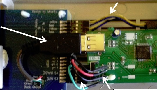
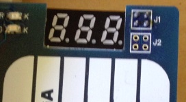
| Attaching the cables. After all adhesive has set, you can attach the remainder of the cables. Note that it will be impossible to attach your existing diskette power and data cables (they are too short) so we have given you 40cm cables. We have not discussed the numeric display cable yet. This does not need to be modified. It stays connected to the GB JK and J7 terminals, and the other end connects to the EB JK and J7. Make sure you get the two 2-pin connectors the right way round. They are marked yellow and black at the EB termainals but we have seen some with white leads instead of yellow. After you have attached all cables, take time for a final inspection to check that all cables are connected and the LED terminals are not shorting out. Time to put your case back together! |
| There is nothing really to say about the
operation of your new Gotek Extension Board except that it works in exactly the same way as a
standalone Gotek drive. Enjoy! Kevin. |